Panorama180 Render : Algorithm

Developer : ft-lab (Yutaka Yoshisaka).
03/04/2019 - 06/15/2021.

Back

This document used the google translation.


Expansion of the panorama's Equirectangular format is performed by the following algorithm.
There are two things: deployment like a VR180 camera and deployment taking parallax into account when turning left and right.

Panorama360-3D, which was added in Panorama180 Render ver. 2.0.0, uses the same basic part of the algorithm, but I have not described the algorithm yet.

Deployment like a VR180 camera

In the VR180 camera, two fisheye lenses are placed at a distance of IPD (pupillary distance).

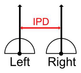
IPD often uses 64 mm.
The method of placing the image from the fisheye lens or the image converted into Equirectangular on the left and right is often used for VR180 camera.

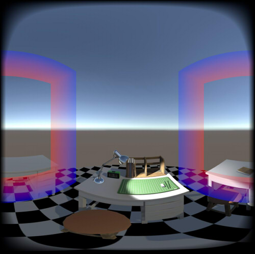
The following is Equirectangular.

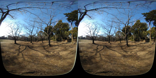
In the VR180 format, information such as projection method and arrangement method is given as "metadata" to this image.

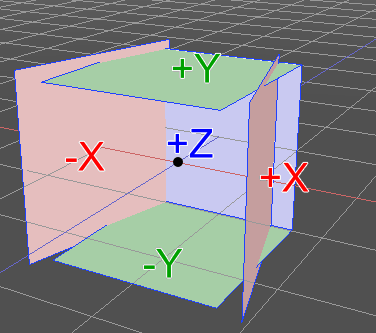
When generating an image of Equirectangular by rendering, we did the following procedure.
The configuration is a cube map that does not use the -Z plane.

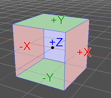
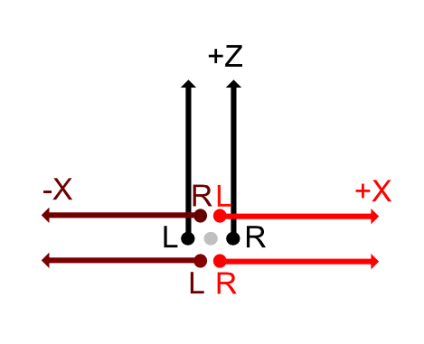
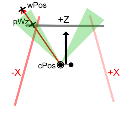
Looking down from above it will be as follows.

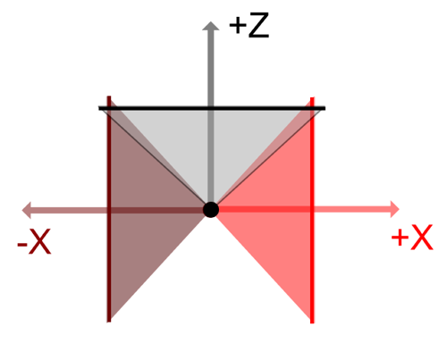
Each camera renders with five cameras facing +Z/-X/+X direction, -Y/+Y direction from the camera center.
Hemispherically scan from the camera and adopt the color of the part that intersects the projection plane of the camera.

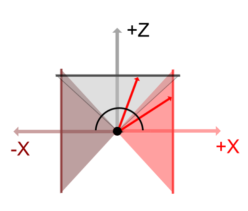
The field of view is set to 95 degrees instead of 90 degrees, and the part where the boundary part overlaps is corrected so that it looks smooth.

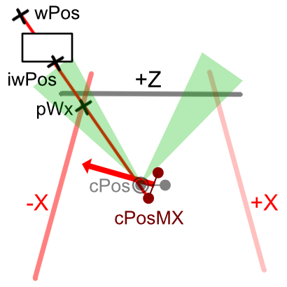
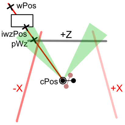
Considering the left and right viewpoints, the +Z direction is parallel and is separated by the IPD distance as follows.

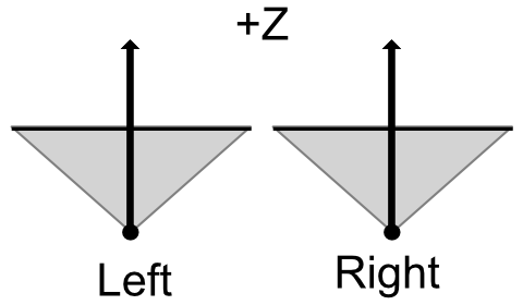
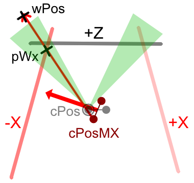
In the -X direction, the position of the camera does not change and it points in the -X direction.

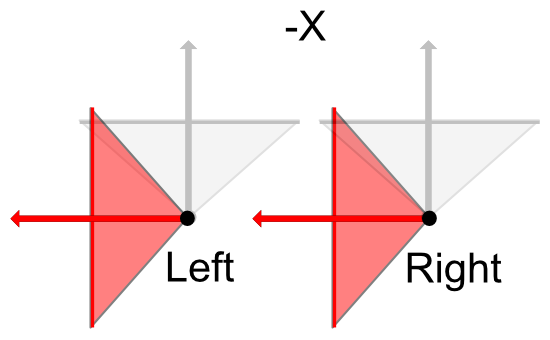
The same is true for +X direction.

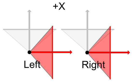
When rendering like the VR180 camera,
Even if the center of the left and right cameras is oriented in any direction, it is the same position just by the IPD distance.
From this, parallax for IPD is generated for the +Z/-Y/+Y plane, but with respect to the -X/+X plane, the cameras are merely displaced back and forth relative to each other, and parallax does not occur.
When viewing by VR as stereoscopic viewing, parallax is reflected correctly when facing the front and up and down,
It leads to a phenomenon that disparity disappears as turning to the left and right.
This is the same phenomenon even when shooting with only two physical fisheye lenses.

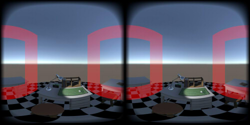
The rendering result is Equirectangular as follows.

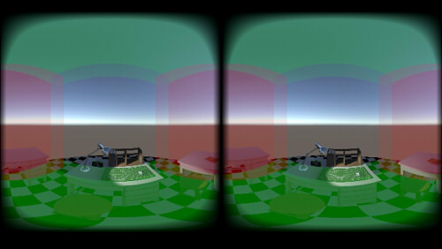
For the sake of clarity, -X/+X is red, and -Y/+Y is green.
In the case of this rendering, it is not necessary to stitch the boundary part because the positions of the left and right cameras are the same.

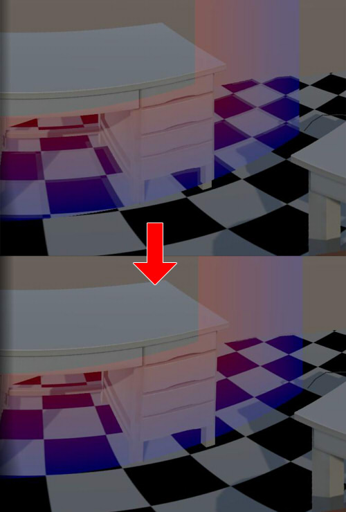
Correction of boundary part

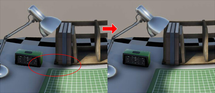
If Post Processing is assigned to each cube map faces,
there will be portions that do not connect at the boundary of each faces.
To alleviate this, the boundary part was corrected by giving a weight value.
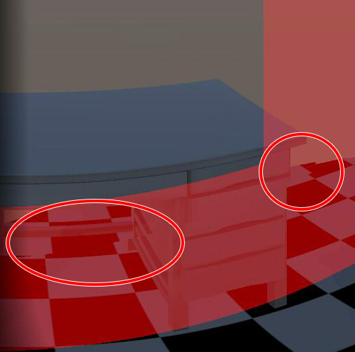
Below, the boundary part is made red.

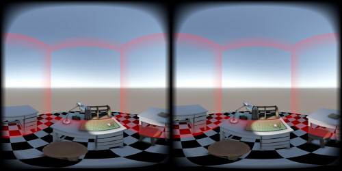
The boundary part is given a fixed position (angle by spherical projection) in advance.

If you simply synthesize the cube map faces,
When the influence of Ambient Occlusion or Bloom is large, breaks in the boundary portion are visible.
In order to solve this, interpolate by giving a weight value to the boundary so that the boundary is not conspicuous.


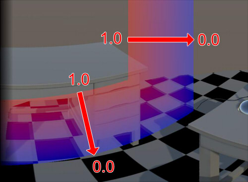
In the case of the lower image, the weight value approaches 1.0 at the boundary where it is in contact with the +Z plane,
and the portion that is in contact with the -Y plane approaches 0.0.

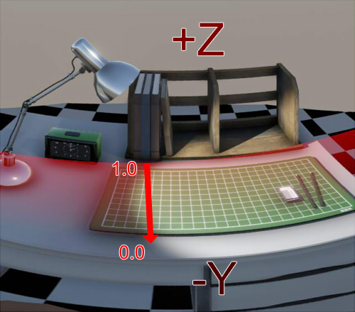
If it is not a boundary, the weight value is 0.0.

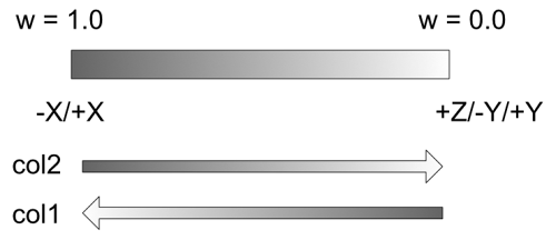
In the boundary part, since the +Z/-Y planes overlap with each other,
You can acquire the pixel color (col1) on the +Z plane and the pixel color (col2) on the -Y plane in advance.
If the weight value is w, it is corrected with the following formula.
float3 col = col2 * (1.0 - w) + col1 * w;
-Y/+Y/-X/+X planes in contact with +Z plane,
-X/+X planes in contact with -Y plane,
-X/+X planes in contact with +Y plane,
Give each boundary part to correct.
By doing this, it relaxes the color difference at the border of Post Processing to some extent.

Deployment considering left and right parallax

This method requires RGB texture and depth texture of the cube map.

When deploying like the VR180 camera described above, the parallax disappears as going to the left and right.
Here, we correct so that parallax appears even if it faces left and right.
Move the center of the left and right eyes as the center of rotation and change the direction and shift it by IPD.

"L" is Left, "R" is Right.

The +Z/-Y/+Y plane as a cube map is the same as when deploying like a VR180 camera, and the centers of the left and right cameras are unchanged.
The -X/+X plane has the same orientation as the VR180 camera, but the centers of the left and right cameras are changing.

Cube map structure

Also, because the parallax changes greatly between the +Z/-Y/+Y planes and the -X/+X planes, the change becomes steep at that boundary.
At that time, burden is imposed on the eyes when viewed as stereoscopic viewing with VR-HMD.
To alleviate this, the -X/+X plane and the line of sight of the camera are tilted inward.

The field of view is slightly enlarged so that it can overlap with the +Z/-Y/+Y planes which is in contact with the cube map faces of -X/+X.

Boundary shift

When camera position is different when rendering to Equirectangular from cube map,
A deviation occurs at the boundary of each cube map faces.
For the following images, the red part is the border.
The boundary of -X/+X planes becomes the place where correction is necessary.

The boundary is always fixed when viewed from the screen even if the camera moves / rotates.
This part is given a fixed position (angle by spherical projection) in advance.
When you enlarge it, you can see where it is misaligned.

We need to stitch this part.

Border stitching

When the cube map faces is rendered, since the viewing angle is set to be larger than 90 degrees to provide overlapping parts,
Combining overlapping parts makes it possible to make the boundary inconspicuous.
Simply combining will result in the following blurring.

This state becomes conspicuous when seen with VR-HMD.

In order to alleviate this, Weight was given to the boundary so as to displace it.
I will call this "Stitch with border weight".
The boundary allocates a fixed value at the angle of the equirectangular sphere projection on the screen.
The lower image is made red as it is closer to the -X/+X planes, and it is made blue as it is closer to the +Z/-Y/+Y planes.

Assuming that the closer to the -X/+X planes, the closer to 1.0, the closer to the +Z/-Y/+Y planes, the closer to 0.0,
We set the part which is not the boundary part to the weight value of 0.0.
Use the cube map faces as it is at the place which is not the boundary (where the weight value is 0.0).
Correction processing is performed at the boundary.

The bottom image is a view from the top.

cPos is the center of the left eye camera.
The boundary of the cube map surfaces is shown in green.
Let wPos be the position on world coordinates scanned on the hemisphere, centered on cPos.
This wPos is located far enough from cPos.
Let pWz be the position where the straight line and the +Z plane intersect from cPos to wPos.

Also, when scanning the -X plane, the position and orientation of the camera change.
Let camera position at this time be cPosMX.

Let pWx be the position where the line on the straight line from cPosMX toward wPos and the -X plane intersect.

The intersection point pWz of the +Z plane viewed from cPos,
The intersection point pWX of the -X plane seen from cPosMX,
From this information, interpolate based on the weight value on the boundary.
When the weight value is close to 0.0, adopt the pixel value of the intersection point pWz of the +Z plane.
When the weight value is close to 1.0, adopt the pixel value of the intersection pWx of the -X plane.

Since pWz is a projection on the +Z plane and pWx is on the -X plane, we convert it to world coordinates with reference to the depth buffer.
In this case, if both are to reach the background, a simple composition is performed.
float3 sPos1 = Convert wPos to texture position on +Z plane seen from cPos;
float3 sPos2 = Convert wPos to texture position on -X plane seen from cPosMX;
float3 col1 = tex2D(Texture of +Z plane, sPos1.xy).rgb; 
float3 col2 = tex2D(Texture of -X plane, sPos2.xy).rgb;
float3 col = (col1 + col2) * 0.5;
Pixels of the background far from the camera are hardly affected by the difference in position such as parallax between the left and right of the camera and cPos / cPosMX.

From the depth buffer on the -X plane,
Calculate the position iwPos that collides with the object from the position of pWx.
iwPos is the position on world coordinates.

Calculate where the iwPos is projected on the +Z plane.
// Distance to the background far away from the camera.
float _FarDistance = 500.0;

// The difference distance of the center of the cameras.
float3 dd = cPos - cPosMX;

// Convert iwPos to the world coordinate position as seen from the cPos center camera.
float3 iwPos2 = normalize((iwPos - cPosMX) + dd) * _FarDistance + cPos;
In the camera (center cPosMX) that projects the -X plane,
iwPos will change to iwPos2.
However, this iwPos2 is a guessed position, not necessarily the correct position.

Let w be the weight value of the boundary.
The weight value is 1.0 for parts near the -X/+X plane, and 0.0 for places close to the +Z/-Y/+Y plane.

Calculate the interpolated world coordinates at the camera position cPosMX (facing the -X plane) at this time and also calculate the pixel value at that time.
// Interpolate the world position on the boundary.
float3 wPos2 = iwPos * w + iwPos2 * (1.0 - w);

float3 sPos = Convert wPos2 to texture position on -X plane seen from cPosMX;
float3 col2 = tex2D(Texture of -X plane, sPos.xy).rgb;
The color that could be calculated at this time is col2.
This corresponds to the color when the weight value changes from 1.0 to 0.0.
Since it will be incorrect when approaching 0.0,
Next, do the same processing on the +Z plane in the opposite direction.

From the depth buffer on the +Z plane, Calculate the position iwzPos that collides with the object from the position of pWz.
iwzPos is the position on the world coordinates.

Calculate to which position the iwzPos is projected on the -X plane.
// Distance to the background far away from the camera.
float _FarDistance = 500.0;

// The difference distance of the center of the cameras.
float3 dd = cPos - cPosMX;

// Convert iwzPos to the world coordinate position as seen from the cPosMX center camera.
float3 iwzPos2 = normalize((iwzPos - cPos) - dd) * _FarDistance + cPosMX;
In the camera (center cPos) projecting the +Z plane, iwzPos will change to iwzPos2.
However, this iwzPos2 is a guessed position, not necessarily the correct position.

Calculate the interpolated world coordinates at the camera position cPos (facing the +Z plane) at this time and also calculate the pixel value at that time.
// Interpolate the world position on the boundary.
float3 wzPos2 = iwzPos * (1.0 - w) + iwzPos2 * w;

float3 sPos = Convert wzPos2 to texture position on +Z plane seen from cPos;
float3 col1 = tex2D(Texture of +Z plane, sPos.xy).rgb;
The color that could be calculated at this time is col1.
This corresponds to the color when the weight value changes from 0.0 to 1.0.
The following two colors have been sought.

Combine this based on the weight value.
float3 col = col2 * w + col1 * (1.0 - w);			
Calculated col corresponds to the interpolated color information on the boundary.
Comparing before and after correction, it changed as follows.


With this alone, there may be a gap left at the position close to the camera.
When the pixel value being scanned on the +Z/-Y/+Y plane is taken as baseCol, When w is smaller than 0.5, perform the following synthesis process and overlap.
float3 sPos1 = Convert wPos to texture position on +Z plane seen from cPos;
float3 baseCol = tex2D(Texture of +Z plane, sPos1.xy).rgb; 

if (w < 0.5) {
  float w2 = w / 0.5;
  col = baseCol * (1.0 - w2) + col * w2;
}
As described above, by using the rendering information (RGB + Depth) with different parallax (the center of the camera is different) To some extent you can smooth the stitch.
If there is a background where depth can not be calculated, an error may appear.

Back