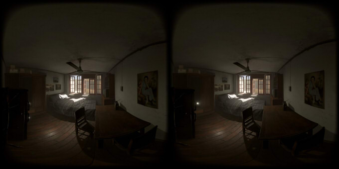
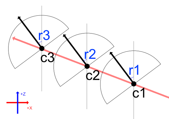
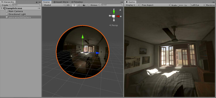
In the scene used as VR, the +Z direction is forward.
The initial rotation of the camera is (0, 0, 0).
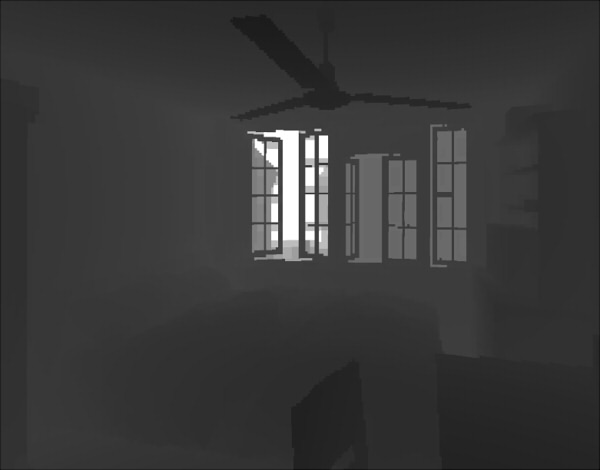
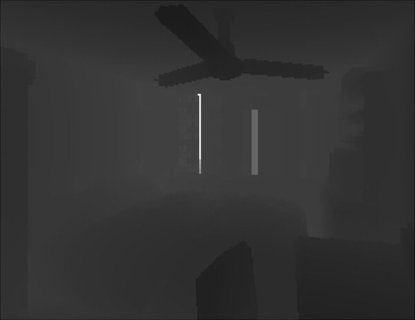
Use "Spatial cache" as a resource and UV map Equirectangular's 180 degree panorama to a hemispheric part against a sphere as a background image.
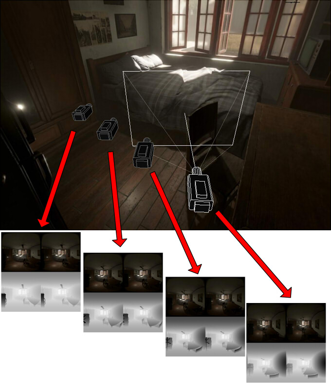
At this time, most background images that are not at the camera position in "Spatial cache" are interpolated and reproduced in real time using Shader.
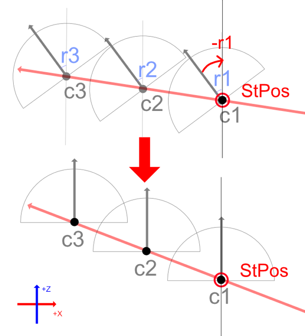
However, keep in mind that it is constrained on a straight line.
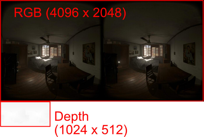
When drawing a panorama image UV-mapped to a sphere as Equirectangular as a background, the fragment shader will scan every pixel.
At this time, one direction of the Shader's 180 degree panorama can be calculated from the UV value.
float3 calcVDir (float2 _uv) {
  float theta = UNITY_PI2 * (_uv.x - 0.5);
  float phi   = UNITY_PI * (_uv.y - 0.5);
  float sinP = sin(phi);
  float cosP = cos(phi);
  float sinT = sin(theta);
  float cosT = cos(theta);
  float3 vDir = float3(cosP * sinT, sinP, cosP * cosT);
  return vDir;
}
UNITY_PI is a constant value of PI (3.141592 ...). UNITY_PI2 is (UNITY_PI * 2.0).
It calculates direction vector from polar coordinates.
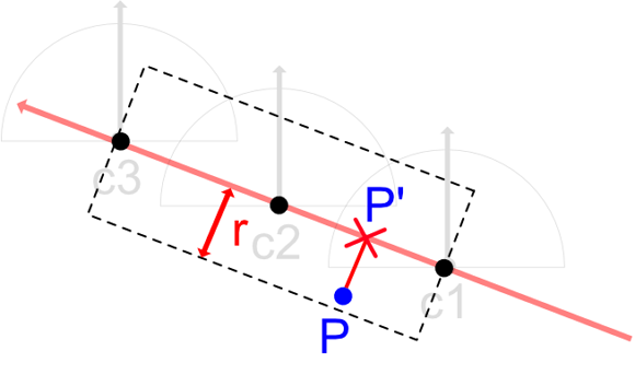
Throw rays from cameras c1 and c2 using the direction vector vDir calculated from UV, and calculate the intersection position in world coordinates with reference to Depth.
"Throw rays" here does not mean shooting as ray tracing,
but it is the process of calculating UV from the direction vector and calculating the depth value at that position.
To calculate UV from world position, do the following:
It will be the reverse of the operation of "one direction of the Shader's 180 degree panorama can be calculated from the UV value" mentioned above.
float2 calcWPosToUV (float3 wPos, float3 centerPos) {
  float3 vDir = normalize(wPos - centerPos);
  float sinP = vDir.y;
  float phi = asin(sinP);    // from -PI/2 to +PI/2 (-90 to +90 degrees).
  float cosP = cos(phi);
  if (abs(cosP) < 1e-5) cosP = 1e-5;
  float sinT = vDir.x / cosP;
  float cosT = vDir.z / cosP;
  sinT = max(sinT, -1.0);
  sinT = min(sinT,  1.0);
  cosT = max(cosT, -1.0);
  cosT = min(cosT,  1.0);
  float a_s = asin(sinT);
  float a_c = acos(cosT);
  float theta = (a_s >= 0.0) ? a_c : (UNITY_PI2 - a_c);

  float2 uv = float2((theta / UNITY_PI2) + 0.5, (phi / UNITY_PI) + 0.5);
  if (uv.x < 0.0) uv.x += 1.0;
  if (uv.x > 1.0) uv.x -= 1.0;
  return uv;
}
Depth values can be obtained using UV from the depth texture.
float depth1 = tex2D(_TexDepth1, uv).r;
float depth2 = tex2D(_TexDepth2, uv).r;
_TexDepth1 is the Depth texture at the camera position of c1.
_TexDepth2 is the Depth texture at the camera position of c2.
This is the same procedure as getting colors from RGB textures. However, for depth value acquisition, do not perform linear interpolation between pixels.
The value of 1 pixel in the Depth texture contains a value between 0.0 and 1.0, which is converted to Z distance in view coordinates by the following formula.
float zDist1 = (depth1 >= 0.99999) ? farPlane : (nearPlane / (1.0 - depth1));
float zDist2 = (depth2 >= 0.99999) ? farPlane : (nearPlane / (1.0 - depth2));
The world coordinate position is calculated from the Z distance.
float3 wPos1 = (vDir * zDist1) + c1;
float3 wPos2 = (vDir * zDist2) + c2;
The following is a function that calculates the collision position in world coordinates taking into account the depth of a specified camera from the UV value.
/**
 * Calculate colliding world coordinate position from UV position and direction vector.
 * @param[in] depthTex  Depth texture.
 * @param[in] uv        UV value.
 * @param[in] cPos      Center of the camera in world coordinates.
 * @param[in] vDir      Direction vector.
 */
float3 calcUVToWorldPos (sampler2D depthTex, float2 uv, float3 cPos, float3 vDir) {
  float depth = tex2D(depthTex, uv).r;

  // Convert from depth value to distance from camera.
  depth = (depth >= 0.99999) ? farPlane : (nearPlane / (1.0 - depth));
  depth = min(depth, farPlane);

  // World coordinate position where it collided.
  return (vDir * depth) + cPos;
}
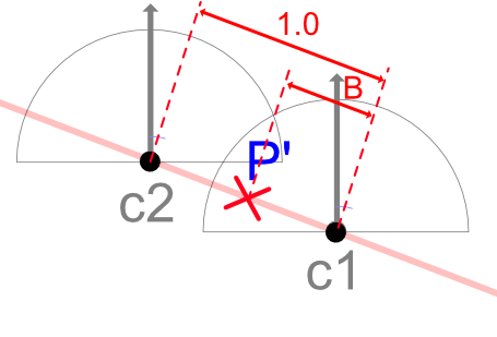
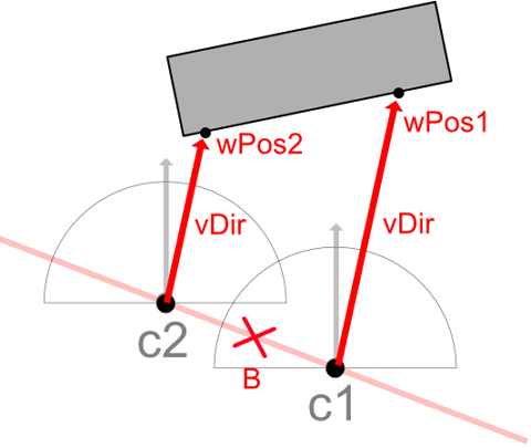
When wPos1 to wPos2 are connected in a straight line (in case of a linear transition), the intersection position at position B can be calculated as follows.
float3 wPosC = lerp(wPos1, wPos2, B);
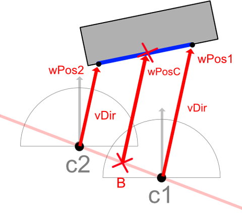
It is unknown whether this wPosC is a correct value at this stage.
At this time, to check whether wPosC is correct, it is judged whether wPosC exists on the line segment extended in the direction of vDir from the position of B and is visible from the camera c1 or c2.
float3 wPosC0 = lerp(c1, c2, B); // World position of B on c1-c2 straight line.
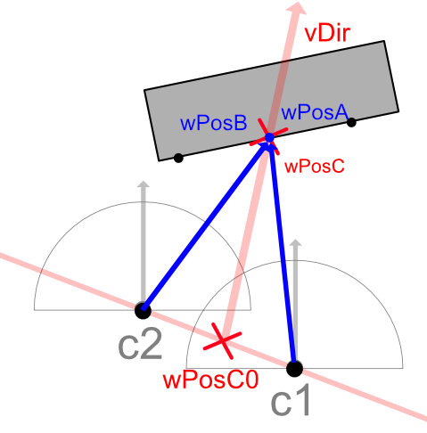
// Convert wPosC in world coordinates to UV value with camera of c1.
float2 newUV1 = calcWPosToUV(wPosC, c1);
// Convert wPosC in world coordinates to UV value with camera of c2.
float2 newUV2 = calcWPosToUV(wPosC, c2);
// Calculate each world coordinate position from UV value.
float3 wPosA = calcUVToWorldPos(_TexDepth1, newUV1, c1, normalize(wPosC - c1));
float3 wPosB = calcUVToWorldPos(_TexDepth2, newUV2, c2, normalize(wPosC - c2));
float angle1 = dot(normalize(wPosA - wPosC0), vDir);
float angle2 = dot(normalize(wPosB - wPosC0), vDir);
If angle1 and angle2 calculated here are infinitely close to 1.0,
it means that wPosC is a collision that is on the straight line of vDir and is visible from the camera position of c1 or c2.
In other words, it is possible to obtain the color of the pixel from the UV values of newUV1 and newUV2 calculated here.
// Let RGB texture in c1 be _Tex1, RGB texture in c2 be _Tex2.
// Get pixel color from calculated UV.
float4 col1 = tex2D(_Tex1, newUV1);
float4 col2 = tex2D(_Tex2, newUV2);
float4 col = float4(0, 0, 0, 1);
if (angle1 > 0.99999 && angle2 > 0.99999) {
  col = lerp(col1, col2, B);
}
It is not always linear during wPos1-wPos2.
If there is unevenness as shown below,
it can be confirmed that wPosA and wPosB calculated in consideration of Depth do not exist on the straight line extended in the vDir direction from wPosC0.
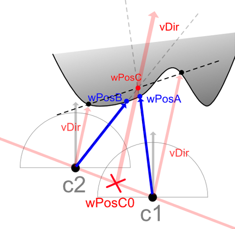
Also, there are cases where only wPosA seen from the camera of c1 exists on a straight line extended in the direction of vPos from wPosC0 (or vice versa).

In this case, there is sampling information that can be seen from the camera of c1, but it can not be seen from the camera of c2.
In this case, the pixel color is adopted from the RGB texture in the c1 camera.
// Get pixel color from calculated UV.
float4 col1 = tex2D(_Tex1, newUV1);
float4 col2 = tex2D(_Tex2, newUV2);
float4 col = float4(0, 0, 0, 1);
if (angle1 > 0.99999 && angle2 <= 0.99999) {
  col = col1;
} else if (angle2 > 0.99999 && angle1 <= 0.99999) {
  col = col2;
}
In summary, the judgment of whether the estimated intersection position wPosC is correct has the following four patterns.
- Success : wPosC is visible from any of the c1/c2 camera positions.
- Success : wPosC is visible from the camera position of c1.
- Success : wPosC is visible from the camera position of c2.
- Failure : wPosC is not visible from either c1/c2 camera position.
These are patterns that work well when wPos1 to wPos2 transition linearly,
assuming that a collision from the camera c1 in the vDir direction is wPos1, and a collision from the camera c2 in the vDir direction is wPos2.
Most of the pixel-by-pixel spatial interpolations can infer the correctly interpolated pixel colors in this way.
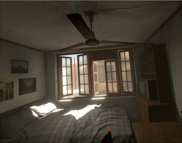
The following shows the error part in red.
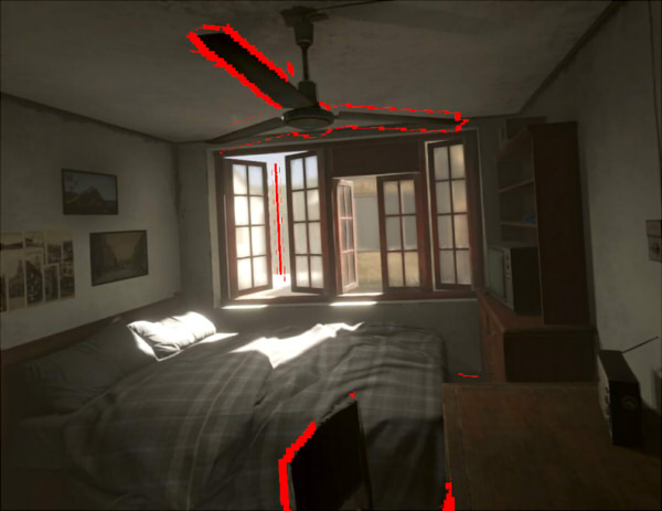
Let's adjust the pixel that got an error a little more.
Using the Z distance calculated from the Depth value used when calculating wPos1 and wPos2, calculate the smaller distance (minDepth) and the larger distance (maxDepth).
Calculate the position on the straight line in the direction of vDir from wPosC0, and set it as wPosC1 and wPosC2.
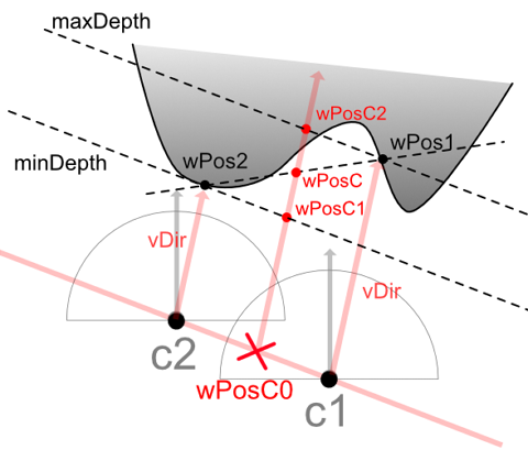
Calculate whether this wPosC1 and wPosC2 are seen from the camera of c1 or c2.
In the case of the above figure, wPosC2 is closer to the desired value than wPosC.
wPosC checks if the estimated value is correct, wPosC1 checks if the estimated value is correct, and wPosC2 checks if the estimated value is correct,
it can be confirmed that the error location (red pixel) is reduced.
Since there are few remaining pixels in error,
when simply combining two pixel colors obtained from the calculated UV value with the value of B, it becomes as follows.
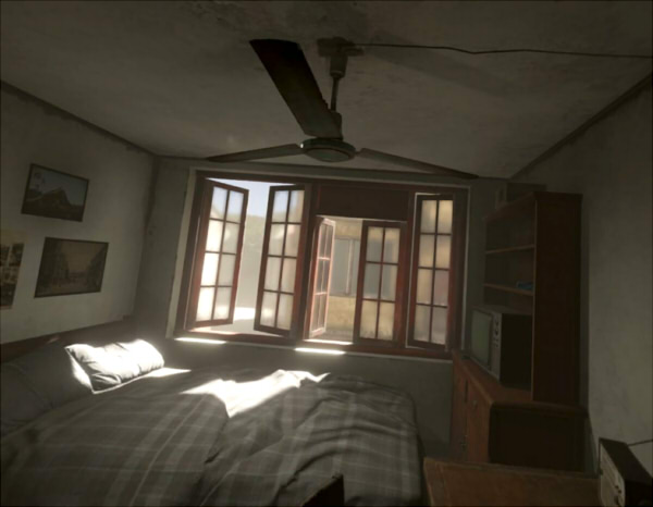
With the above, it has been confirmed that if there are RGB/Depth textures from two cameras, spatial interpolation can be performed to some extent.
If the camera position of the panoramic image sampled by "Spatial cache" is far (when the number of samplings is insufficient), errors will increase.
Alternatively, if the pixel-to-pixel transition as the camera moves from c1 to c2 is not linear, it may be conceivable to create a rough look-up table (texture) by preprocessing and reference it.
In addition, although linear interpolation from two cameras is used in this explanation, it may be possible to increase the freedom of movement by interpolation from two or more cameras.